We’ve recently acquired a pair of non-functioning Commodore VIC-20 and are looking at fixing them, but quickly realized we’d need an AC-AC transformer.
Power Transformer
The original VIC-20 AC power transformer pop online for auction from time to time, but prices are ridiculously high. Replacing the original brick simply requires an appropriate AC transformer; which is much less complicated than replacing a C64 power brick, or a Colecovision power brick. Readings online suggest to have a transformer of at least 3A in the 9-12VAC range. Sadly, the 9VAC section of the C64 power brick is only 1A, much too low to properly supply the AC-only VIC-20. The spare parts bin does have a few 9VAC and 12VAC wall warts, but the strongest one was 2A, which is also too weak.
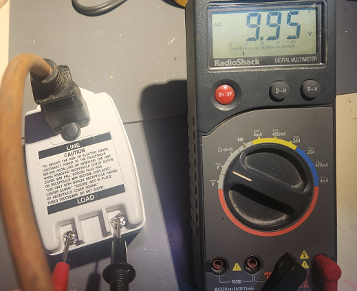
There are a multitude of 9-to-12 VAC transformers available online, some more practical than others. Some pricier than others. Some much bigger than others. One that seemed practical and economical was meant for alarm systems, rated 9VAC 3.34A; hopefully more than what’s required. Upon reception we quickly tested its output to read a satisfying 9.95 VAC without loads.

Power Connector
To connect to the VIC, the proper connector is needed. In these VIC model, the connector also include an imbedded switch – likely the specific power receptacle was also used on some battery-operated apparatus and that insertion-switch was used to disconnect batteries and connect AC power.
Nevertheless the correct size is required for pin connection, but also to activate the switch and permit power to reach the PCB. Not every 8-shape connector would fit the bill.
There are somewhat similar connectors on apparatus here and there, including IKEA (no affiliations with wereallgeeks) but none seemed to have the proper physical sizes and pin sizes to work correctly.

In the end the spare parts bin served – a few old radio power plugs fit perfectly. Apparently some razor plugs also work well, but the hunt ended with our radio plugs.

Splicing this cable and screwing it to the power brick’s power output is all that’s needed to proceed with testing.
Safety first
Before proceeding… some of those chips are well over 40 years of age now. The CPU, VIC (Video Interface Chip) and VIAs (Versatile Interface Adapters) as well as all the ROMs are socketed on both boards, so we pulled them out.
The board with the mention “bad VIC” had the VIC inserted with a pin pulled out.

The pin seems to have been pin 18, which is one of the paddle potentiometer pins so this should not have prevented normal operations.
We labelled the VIC-20 with the “dead VIC” mention as #1, and the other “graphic mess” as #2. The chips also got markings to differentiate them from one another.

With all the chips pulled, we could test the main power circuit. The 9VAC reads clean when the switch is off, but it reduces to just above 5VAC with the added load of the motherboard as soon as it is powered on. This seems on the low side. There was similar readings on both VIC-20s

That said, testing at multiple locations proves the 5V DC rail to be appropriate, on both units, as well as the user port 9VAC output.
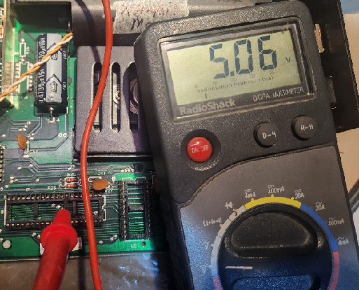


VIC20#1 has 4.89VDC and VIC20#2 has 5.05VDC. With the power block and power conversion circuit giving these readings, we feel safe to continue with testing.
Stay tuned