Having a valid clock signal will quickly lead to validating the 6560 VIC chip and 6502 CPU; but for that to happen we will quickly require a valid set of ROM chips. Are the ROM on our VIC-20s valid?
Similarly to the Commodore 64, the VIC-20 has 3 ROM:
the Character ROM to display something legible by humans – in theory somewhat similar between the two systems;
the BASIC ROM to let humans program in BASIC, but also serves as the main command line interface of the computer, and those are tied to the machine’s Kernal;
and the Kernal ROM – yes, kernal with an A – that’s how Commodore named it.
While these are generally reliable, they can fail. More specifically, one of our PCB’s ROM chips came with masking tape that has a big X and a question mark on it, making it very doubtful that it could be a usable chip. Are others also meant to have such a masking tape question and X mark?
X marks the spot? Doubtful Kernal ROM on VIC20#1
An easy way to test would be to put them in a working VIC-20 and see what’s going on… but without an available working VIC-20, something that can be done is dumping them to file in order to read the content.
Adapter to put an 2532 in modern programmer and program them as 2732VIC20#2 character ROM dump
With the adapter, it reads as an 2732 EPROM. The content of both character ROMs seems to look good.
2364 masked ROM
The Kernal and BASIC ROMs are 2364 masked ROM, We recently made a 2364-2764 adapter for the specific purpose of dumping these ROM chips.
Of 6 chips, 5 seems to read good, with only the X-marked Kernal ROM from VIC20#1 being weird – which isn’t really a surprise.
VIC20#1 Kernal ROM reads garbageDump (garbage) from VIC20#1 Kernal
Binary comparison (we like beyond compare – no affiliations) of the Character ROMs shows they are both identical.
The BASIC ROMs have a total of 2 different bytes (perhaps even bits). Being that Zimmers.net stated there is only 1 version of the BASIC ROM, one of the chip may have slight issues, and maybe cause problems? It may be on the verge of becoming a bigger problem, or could work as-is for years. Who knows.
One Kernal ROM being already declared as bad makes that we have no comparison to make between the two, but we can download rom dumps from the interwebs…
Binary comparing the files with the binaries from Zimmers.net, we can attest the character ROMs are OK✓
We can also know for sure that it is the VIC20#1 BASICROM that has 2 bits wrong – is it a problem?
and finally, we can confirm that the VIC20#2 kernal fully matches kernal.901486-06.bin. ✓
So, all VIC20#2 ROMs checks OK ✓✓✓ !
At this point, we can declare a dead Kernal ROM and a doubtful BASIC ROM. — At least we have a full set to continue testing.
Dead component score:
VIC20#1 : 2 dead chips + 1 broken crystal + 1 doubtful chip
VIC20#2 : 0
Way before the days of global interconnection known as the world-wide-web, before Internet Protocol, before web browsers, there was site-to-site modem connections, and geeks from all around the globe would remotely connect to their local Bulletin Board Systems, commonly referred to as simply BBS.
The BBS scene was were to get latest software, music, news and demos.
Back in the 90s and 80s, 8-bit computers were often used for that. And some are still online today.
To get a CPU running – a 6502 in this case – you need a few things.
power (VCC near 5VDC)
Reset circuitry (reset at first, then not reset)
Clock (1Mhz)
We already tested the VCC to look good, at least without the chips. It will have to be re-tested every time we add or remove chips to make sure all is good. If we had another working VIC-20 we could test the chips on the known working unit – but this is not the case here. Something may have to be done about this.
Reset Circuit
While we have the chips removed, we can test the reset circuit. It is meant to be kept low when we power the unit, and go high only after the system has stabilize, to enable the CPU to begin its work. On the 6502, Notice the line on top of RES – the pin is active low – reset when low, not reset when the pin is high. There is a NE555 (UB6) on the VIC-20 motherboard that holds the RESET low for about 4 seconds, and then brings it high.
MOS 6502 CPU chip pinout
It is possible to poke the voltage at this pin with a voltmeter or oscilloscope to see the behavior while we apply power to the board. This does not show well on picture, but it is low at first, then high after a short while – not officially timed, but 4 seconds sounds right. If the CPU was present, it would know to follow a reset sequence that should end up booting the machine.
We did test this on both PCBs. Both VIC20#1 and VIC20#2 behave accordingly, which is good news.
Clock
The clock circuitry is a bit more complex. It helps to look at the schematics. They are available on zimmers.net. the PCBs are both marked 324003 and reading online we are told the correct schematics would be the 324991-2 available in 3 GIF files on zimmers.net. The first part of the schematics is of interest as we follow the pin labelled Φ0 which is the clock input and is pin 37 of the 6502. Tracing this input signal, we see that it comes from the VIC – similarly to the Commodore 64 with the VIC-2 chip, the VIC chip handles the CPU clock. There is minor circuitry, but the signal will come from VIC’s pin 35 – PΦ1.
MOS 6560 VIC chip pinout
Still, the clock needs to enter the VIC for the VIC to feed a correct clock to the CPU, and this happens on pins Φ1 and Φ2 on pins 38-39. This clock should be visible without the VIC chip socketed, so let’s give it a look.
VIC20#2 was on the bench so we connected power and put the scope between the VIC shield (ground) and VIC socket pin 38, then 39, to see what is going on. We but clearly see there is a clock input of some sort. It is outside of the scope’s tracking capability but the oscillation is clearly visible.
Clock signal validation on VIC20#2Clock signal entering VIC chip for VIC20#2
The same test was performed on VIC20#1, but the results differed quite a bit. There is no signal (see below).
Looking at the schematics, we see there is an 7402 IC chip at UB9 that connects the crystal to the VIC chip. The combination of the 7402 chip and crystal makes the input clocks for the VIC, which in turn will divide this to generate a proper CPU clock.
Reading online, it appear this chip is often a problem on these old VIC-20s. If there is not a valid clock going into the VIC chip, there sure won’t be any sort of valid clock going out, to the CPU.
Oscilation error on VIC20#1Schematics shows 7402 is responsible for VIC chip input clock
Another suspect is the crystal Y1 and the few other components, the variable potentiometer at C35 that could have gone off.
Let’s begin by looking at UB9 pins 2-3 and 5-6 where the crystal enters the 7402.
Testing on VIC20#2 to have a comparable, we clearly see activities on 7402 pins 5-6 and on pins 2-3, but the same test on VIC20#1 only shows a rather flat line on pins 5-6 very similar to what goes to its VIC 6560.
Clock signal at 7402 of VIC20#2 – the scope had issues trigerring No activity at 7402 on VIC20#1
At this point, the suspects are the Crystal and/or circuitry bad, or a dead 7402 pulling the input signals low and causing this reading – some investigation is to be done on the clock circuit of VIC20#1.
If the 7402 is bad, it will need to be removed. If it is not, socketing it won’t hurt, but clearly will help trying to understand what is going on. We used the desoldering gun, and removed the chip. Same position tested without the 7402 in place.
Testing clock oscilation circuit on VIC20#1No activity at 7402 on VIC20#1
It made absolutely no change. Perhaps the 7402 is not dead afterall. Testing in the chip programmer proved it is considered as good.
Trying to visually inspect the crystal, variable capacitor and surrounding circuitry, something very odd became apparent. The crystal is not held in place as tightly as it should, and certainly more loose than on the VIC20#2. Now these have 2 pins, plus are held in place by the ground connection soldered at the top.
Not being sure it was still working as expected and wanting to investigate, we started to look at removing it – and sure enough, it was broken – physically. One leg completely broken at the base. Perhaps that is why this motherboard has the mention “BAD VIC”??
Crystal was damaged.There was nothing left to try and solder a replacement tab
Luckily the spare parts bin had a 14.318 Mhz crystal of similar size which was put in place. Apparently 14.31818 being 4x the color burst frequency of NTSC makes is rather common in parts bins. Who would have known?
It happens to also be the base clock crystal used on the Commodore 64 NTSC variants; likely for the same reasons.
With it in place, activity was present at the 7402 input pins; and putting the 7402 in place brings a signal to the 6560. Tweaking the variable cap may be required in the future to fine-tune the signal, but for now we can continue testing the clock signal.
While searching online for information about the VIC-20 clock circuit this thread on 6502.org popped out. While we didn’t have to replace the 7402 on this one, we wondered if it could be swapped by an easier to find 74LS02. Apparently the timings are a little different, which is bad in a clock circuit, and a 74LS02 would not be a good candidate for replacing the UB9 7402 chip. Nor would have a 74HCT02. Suggestion is to find a 7402 or 74F02 replacement.
Good to know.
Let’s write it in the repair log as a reminder for future references. ✓
VIC’s Output clock
Now that both clocks going to their respective VIC chips are working, is time to put them VICs in their sockets and see if the VICs process the clock signal properly.
Adding the chip to its socket for some testing – starting with VIC20#2 and its VICchip#2 we can check the output signals, those sent to the CPU – PΦ1 and PΦ2 at pins 35-36
The clock signal is clearly visible and regular. Same test can be done directly at pin 37 of the CPU socket to ensure the signal out of the VIC chip reaches the CPU.
Sadly, testing the same thing on VIC20#1 with VICchip#1 leads to a rather flat line
Working clock signal out of VICchip#2Testing clock entering the 6502 CPU at its socketNo clock out of VICchip#1
In order to be certain about the state of VICchip#1, we swapped chips between VIC20#1 and VIC20#2 – the VICchip#2 leads a good clock to the CPU socket on VIC20#1; and VICchip#1 leads nothing on both motherboards.
Sadly, VICchip#1 is non-functional. This is sad because the VIC chip is the only chip of the VIC-20 that is not replaceable by modern components; this means it can only be replaced by a VIC chip from a donor board, or a NOS chip, until a modern chip is made.
Dead component score:
VIC20#1 : 1 dead chip + 1 broken crystal
VIC20#2 : 0
At this point, we have all that we need for a CPU to operate – Correct power; Reset signal and Clock. We can begin to plan looking at the CPU.
The original VIC-20 AC power transformer pop online for auction from time to time, but prices are ridiculously high. Replacing the original brick simply requires an appropriate AC transformer; which is much less complicated than replacing a C64 power brick, or a Colecovision power brick. Readings online suggest to have a transformer of at least 3A in the 9-12VAC range. Sadly, the 9VAC section of the C64 power brick is only 1A, much too low to properly supply the AC-only VIC-20. The spare parts bin does have a few 9VAC and 12VAC wall warts, but the strongest one was 2A, which is also too weak.
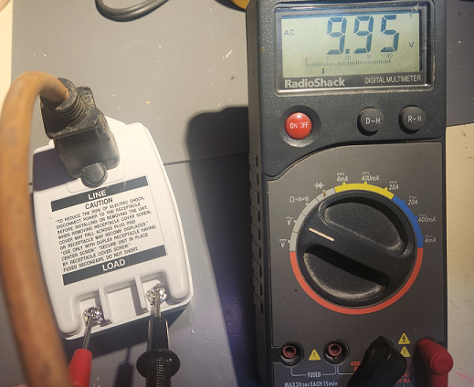
There are a multitude of 9-to-12 VAC transformers available online, some more practical than others. Some pricier than others. Some much bigger than others. One that seemed practical and economical was meant for alarm systems, rated 9VAC 3.34A; hopefully more than what’s required. Upon reception we quickly tested its output to read a satisfying 9.95 VAC without loads.
Alarm system 9VAC 3.34A transformerThe transformer outputs a nice 9.95VAC without load.
Power Connector
To connect to the VIC, the proper connector is needed. In these VIC model, the connector also include an imbedded switch – likely the specific power receptacle was also used on some battery-operated apparatus and that insertion-switch was used to disconnect batteries and connect AC power.
Nevertheless the correct size is required for pin connection, but also to activate the switch and permit power to reach the PCB. Not every 8-shape connector would fit the bill.
There are somewhat similar connectors on apparatus here and there, including IKEA (no affiliations with wereallgeeks) but none seemed to have the proper physical sizes and pin sizes to work correctly.
Various connectors
In the end the spare parts bin served – a few old radio power plugs fit perfectly. Apparently some razor plugs also work well, but the hunt ended with our radio plugs.
Recycling radio plug for VIC-20
Splicing this cable and screwing it to the power brick’s power output is all that’s needed to proceed with testing.
Safety first
Before proceeding… some of those chips are well over 40 years of age now. The CPU, VIC (Video Interface Chip) and VIAs (Versatile Interface Adapters) as well as all the ROMs are socketed on both boards, so we pulled them out.
The board with the mention “bad VIC” had the VIC inserted with a pin pulled out.
VIC-chip with a bent pin.
The pin seems to have been pin 18, which is one of the paddle potentiometer pins so this should not have prevented normal operations.
We labelled the VIC-20 with the “dead VIC” mention as #1, and the other “graphic mess” as #2. The chips also got markings to differentiate them from one another.
Labelled VIC boards and chips
With all the chips pulled, we could test the main power circuit. The 9VAC reads clean when the switch is off, but it reduces to just above 5VAC with the added load of the motherboard as soon as it is powered on. This seems on the low side. There was similar readings on both VIC-20s
AC Brick reads just above 5VAC with load
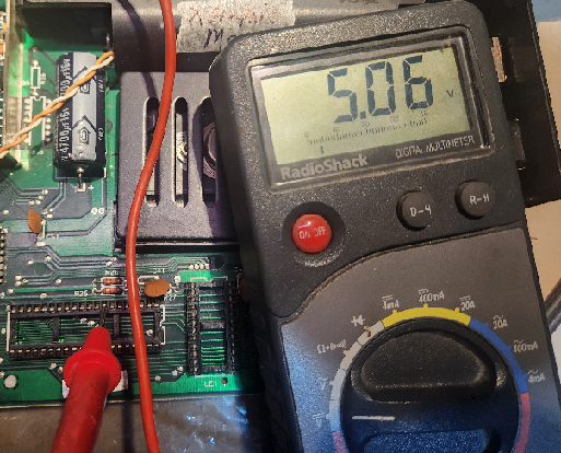
That said, testing at multiple locations proves the 5V DC rail to be appropriate, on both units, as well as the user port 9VAC output.
5VDC at MOS 6502 CPU5VDC at VIC-20’s user port9VAC at VIC-20’s user port
VIC20#1 has 4.89VDC and VIC20#2 has 5.05VDC. With the power block and power conversion circuit giving these readings, we feel safe to continue with testing.


